Repairing the Panasonic RF-B45 All Band Receiver
I just recently found a defect Panasonic RF-B45 All Band Receiver that had been lying in a box waiting to be repaired. The Panasonic RF-B45 is a great little radio that can be run of 6V DC or 4 Alkaline Batteries. It was actually still working, but could not be turned on via the ON/OFF switch, as it was broken. I disassembled the device and found that the keyboard uses cheap radial tactile switches that could be easily replaced. I ordered 30 new "ALPS" switches from China, reassembled the device and waited. Finally the switches arrived and I could start replacing them. In the following I will document the necessary steps.
Step 1: Disassembling the receiver
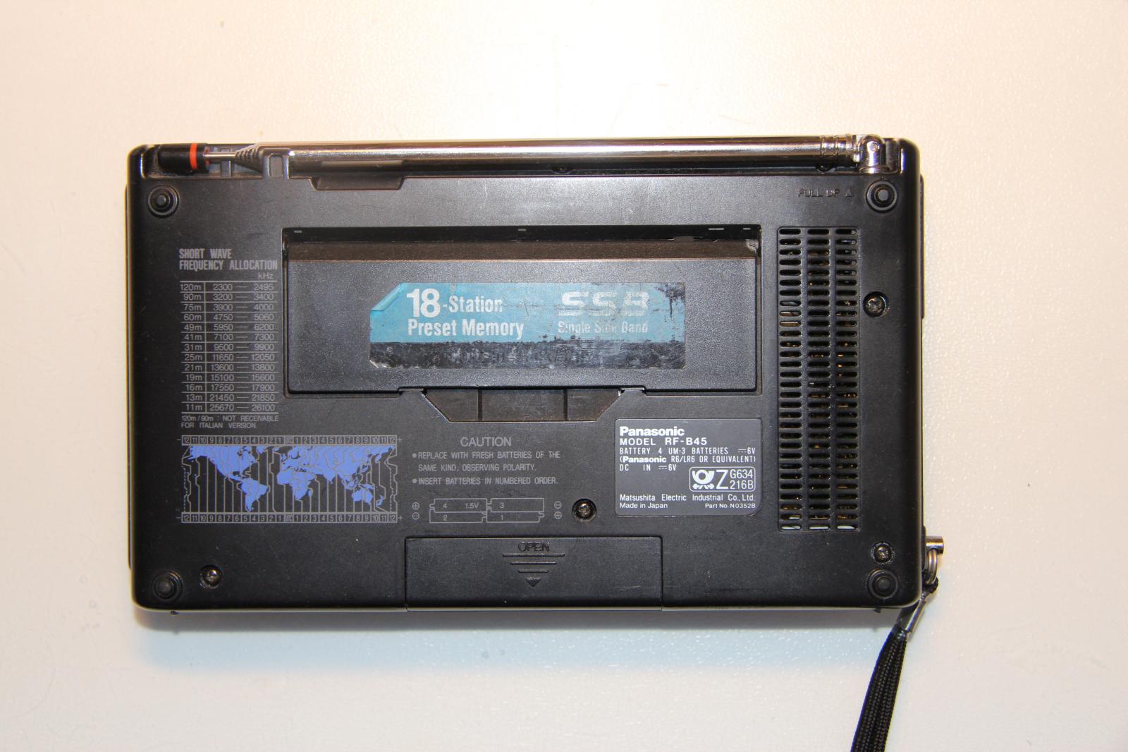

The Panasonic RF-B45 is easily cracked open. Just remove the antenna and then six screws. In the above image I have marked the position of all screws. After the back is taken off the mainboard can be removed.


The switches are on an extra PCB that is connected via a ribbon cable. Remove the connector carefully and then the two screws holding back the PCB. Again, the screws and the connector are marked in the image.
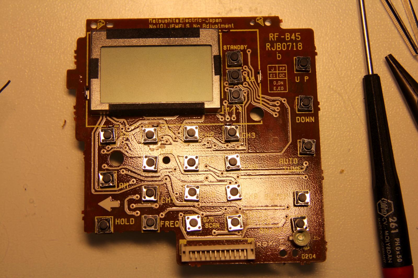
Step 2: Unsoldering the switches

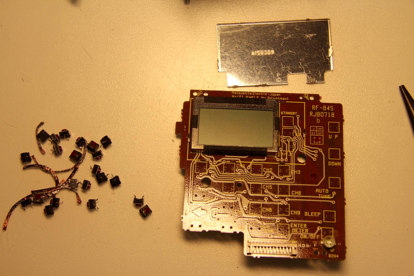
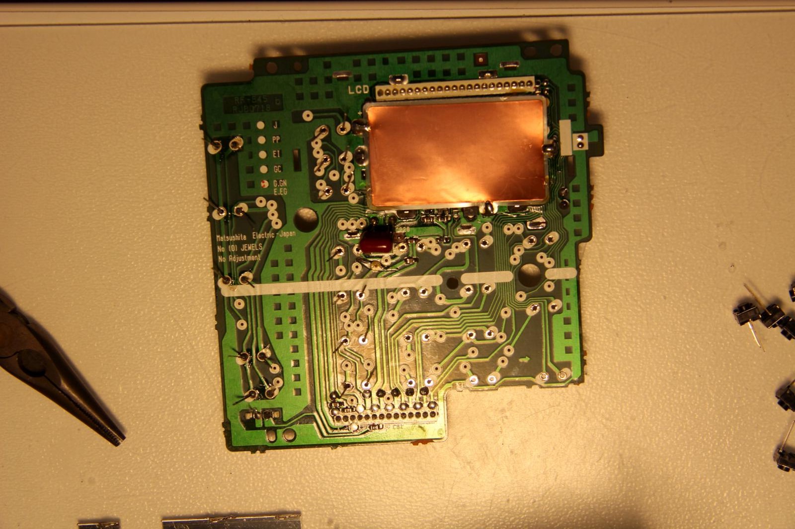
Having the PCB removed one can start the tedious task of unsoldering all switches. You can of course just replace the broken switches, but to be on the safe side I just replaced all of them. One pad lifted from the PCB while I unsoldered the switches, but all in all the PCB endured this procedure quite well. As it is neither plated through nor of FR4 material you have to be careful not to destroy the delicate pads and traces. The metal shield on the back of the LC display covers three switches and therefore has to be removed, too. This is time consuming work but not difficult at all.

Step 3: Soldering the new switches
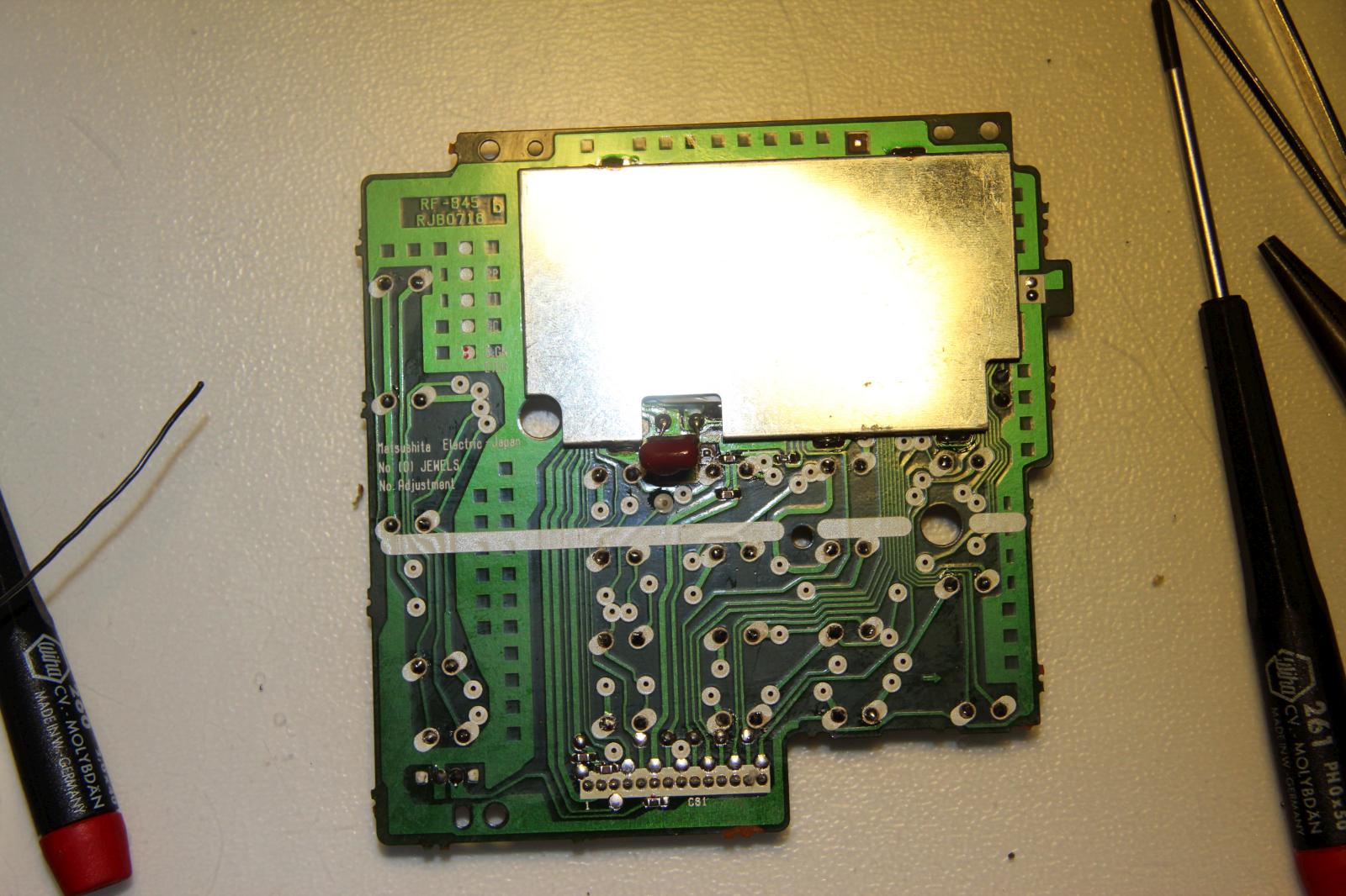
After all switches are gone clean the PCB. Then start soldering the new switches. This again takes some time. I soldered one leg at first, then reflowing the joint and pressing the switch flush to the PCB. I then soldered the second leg. After finishing all joints cut the legs, drown them in flux and reflow them again. Do a short inspection under magnification and make sure that all joints are nice and shiny. Then clean the PCB again.
Step 4: Assembling the device and testing

Now you can put the receiver back together again. Fasten the two screws fixing the PCB and then carefully connect the ribbon cable connector. Put the mainboard back in the front part of the case and put the back on. After all screws are fastened and the antenna is mounted the receiver should be working as normal. Congratulations, you have rescued one more device from going to the landfill.
